search
Search

Enter keywords to search for products, blog posts, and more.

English

Home > 11–35kV Oil Immersed Distribution Transformer (S11/S13 Series)

11–35kV Oil Immersed Distribution Transformer (S11/S13 Series)

11–35kV Oil Immersed Distribution Transformer (S11/S13 Series)

Product Description:
EverWins S11 and S13 series oil immersed distribution transformers operate at rated voltages from 10kV to 35kV with capacities from 30kVA to 2,500kVA. The core uses cold-rolled grain-oriented silicon steel. Windings are available in copper or aluminum with Dyn11 or Yyn0 connections. Both hermetically sealed and conservator type tank structures are in production. These units are designed for outdoor installation in urban, rural and industrial distribution networks operating at 50Hz or 60Hz.
Available Configurations
Single phase and three phase
Hermetically sealed (corrugated tank) or conservator type
No-load tap changer ±5% or ±2×2.5%
On-load tap changer optional
ONAN cooling standard, ONAF optional for higher loads
Special environment codes: P (plateau), C (anti-corrosion), T (dry tropics), H (humid tropics)
Ordering Information
Tell us your rated voltage (HV/LV), capacity, frequency, winding material preference, connection group, installation altitude and ambient temperature range. Our engineering team will confirm the full specification and provide a GA drawing for your approval before production.

Technial Parameters

ParameterS11 SeriesS13 Series
Rated Input Voltage (HV)10 / 11 / 15 / 20 / 22 / 33 / 35 kV10 / 11 / 15 / 20 / 22 / 33 / 35 kV
Rated Output Voltage (LV)0.4 kV, 11 kV0.4 kV, 11 kV
Rated Capacity30 – 2,500 kVA30 – 2,500 kVA
PhaseThree phase (single phase available)Three phase (single phase available)
Frequency50 Hz / 60 Hz50 Hz / 60 Hz
Winding ConnectionDyn11, Yyn0Dyn11, Yyn0
HV Tapping Range±5% or ±2×2.5%±5% or ±2×2.5%
Cooling MethodONANONAN
No-Load Loss (500kVA, 10kV)Ref. S11 standard value~15–20% lower than S11
Load Loss (500kVA, 10kV)Ref. S11 standard value~10–15% lower than S11
Core MaterialCold-rolled grain-oriented silicon steelCold-rolled grain-oriented silicon steel
Winding MaterialCopper or AluminumCopper or Aluminum
Tank StructureHermetically sealed / ConservatorHermetically sealed / Conservator
StandardsIEC 60076, GB/T 6451, GB 20052IEC 60076, GB/T 6451, GB 20052
Ambient Temperature-25°C to +40°C-25°C to +40°C
Altitude≤1000m (high-altitude derating available)≤1000m (high-altitude derating available)


Product Details

TYPE DESIGNATION

The model number tells you exactly what you are ordering. Take S11-M-500/10 as an example:

• S means three phase

• 11 is the design series and energy efficiency level

• M stands for hermetically sealed

• 500 is the rated capacity in kVA

• 10 is the high voltage side in kV

If you see a D prefix, the unit is single phase.F means forced-air cooling is added.C indicates an on-load tap changer.R refers to round (core) core construction.

S13 series follows the same naming rules but meets a higher energy efficiency grade with lower no-load and load losses. When your project specification calls for the latest national energy efficiency standards or when the transformer will run at light load for long hours, S13 is the better fit.


STRUCTURAL DESIGN

CORE

The core is stacked from cold-rolled grain-oriented silicon steel laminations, cut at 45-degree mitered joints to reduce flux leakage at the corners. Laminations are coated with insulating film and clamped with steel structural parts. This clamping design also controls core vibration and keeps operating noise down.

WINDINGS

• High voltage windings use multi-layer cylindrical construction with oxygen-free copper wire or electrical aluminum wire.

• Low voltage windings use foil winding or layer winding depending on the current rating.

• All windings go through vacuum drying and vacuum oil impregnation to remove moisture and air pockets from the insulation.
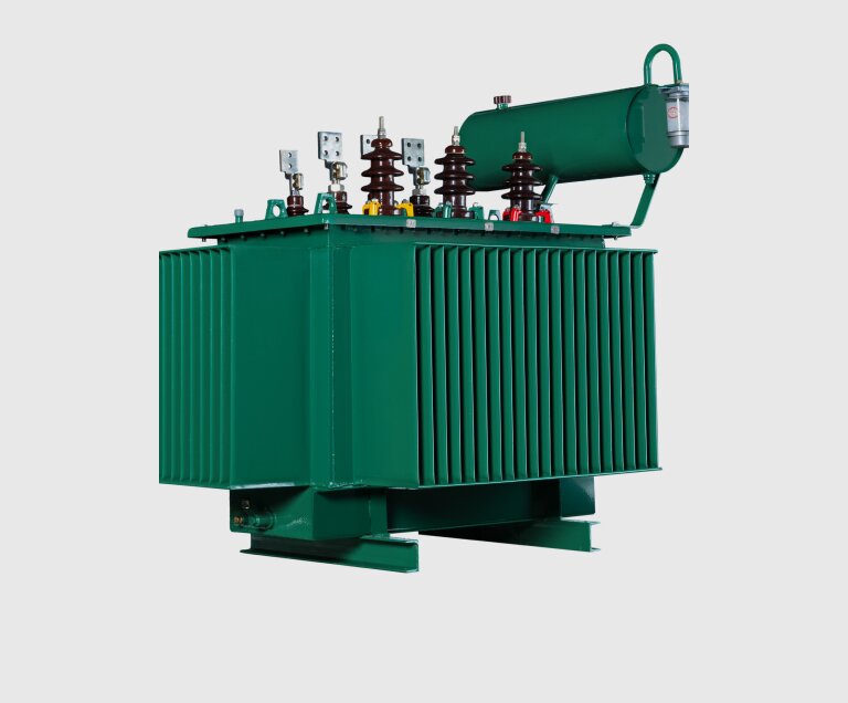
TANK

• Hermetically sealed units use corrugated tank walls that expand and contract with oil temperature changes. No conservator, no breather, no oil-air contact.

• Conservator type units have a separate oil expansion tank with silica gel breather for oil preservation.


S11 VS S13 LOSS COMPARISON

The table below shows typical no-load and load loss values for common capacity ratings. S13 series delivers measurably lower losses at every capacity point. Over the 20–30 year service life of a distribution transformer, the accumulated energy savings from reduced iron and copper losses can be significant — especially for units that stay energized around the clock.

Capacity (kVA)S11 No-Load Loss (W)S13 No-Load Loss (W)S11 Load Loss (W)S13 Load Loss (W)
1002001601,5001,350
3154603803,5003,150
5006805554,9004,400
1,0001,20098010,3009,200
2,5002,6002,10021,50019,200


Related Products